Building U-boot and boot image

Hi Again,

So in the previous steps we’ve built the bitstream and the first stage bootloader now all we need is to build u-boot and we’ll have something to run on our Zybo.  If you’ve been working on a windows machine you’ll need to switch to a Linux machine for these next steps.  It does look like you can build u-boot on windows using the Xilinx SDK software but I used Linux, maybe building u-boot with Windows will be another blog post.  Once you have a virtual machine running Linux or a system running Linux we’ll need to install a couple items before we can start getting and building u-boot.  First, if you have a 64-bit system you’ll have to install the 32-bit libraries for your Linux distro before we can use the code sorcery toolchain.  This link will show you what commands to use based on the flavour of Linux you’ve chosen.  Next make sure you have git installed, we’ll need to use git to download the sources needed to build u-boot and later Linux and Xenomai.  To install Linux on Ubuntu , go to the terminal and type in:

bash> sudo apt-get install git

on red hat based distro

bash> sudo yum install git

Once we’ve got those tools installed it’s time to get our toolchain from Xilinx.  Follow the steps on the Xilinx wiki follow the steps to download and install the command line tools.  We’ll be building u-boot, linux and xenomai all from the command line.  After completing the toolchain install and adding the xilinx tools into our PATH variables we should be able to type

bash> arm-xilinx-linux-gnueabi-gcc

on the command line and get an error saying no input files specified.

  Screenshot from 2014-03-25 10:02:36

If we see this error then everything is setup and we are ready to download U-boot, if not then you’ve probably forgot to add the toolchain location to your PATH variable.  Take a look back at the Xilinx wiki to make sure you’ve exported bothe CROSS_COMPILER variable and your modified PATH variable.

We are now ready to configure u-boot from source for Zybo.  The Xilinx wiki on u-boot is a great resource to get us started.  It’s gear towards the Zed board which is okay because the Zybo is very similar.  I only had to change one piece of source code to get it to work.  I’ve been able to configure u-boot from both the Zed board config and the generic one. I’ll go over it modifying the Zedboard config.  Let’s fetch the source:

bash> git clone git://github.com/Xilinx/u-boot-xlnx.git

Let’s take a look at the config files, in include/configs we should see a file called zynq_zed.h,  this file is how u-boot knows how to configure the system.  Let’s edit this file for zybo, all we have to do is add the following line:

#define CONFIG_ZYNQ_PS_CLK_FREQ 50000000UL

We need to add this because the peripheral clock on the Zybo is 50Mhz, on the Zedboard it’s 33.3Mhz.  I got u-boot to work with and without this change but I’ll add it in here since we need to keep this in mind when we try to get the Linux debug console to work.

Once we’ve saved that file, let’s configure u-boot to build for our target by entering :

‘make zynq_zed_config’

Screenshot from 2014-03-25 10:45:16

type ‘make’ and we should be able to watch the build output and hopefully see no errors.

Screenshot from 2014-03-25 10:48:23

So u-boot is now built, now we need to gather the bitstream from step 1, the first stage boot loader elf file from step 2 and the u-boot executable into one location that the SDK can see.  So if you are doing this on two machines like I am make sure there is a shared folder somewhere that we can put the files.

If we do an ‘ls’ in the u-boot directory we should see a file with no extension named ‘u-boot’.  Copy this file to a separate location.  Rename this file to u-boot.elf

Open the Xilinx SDK, and under the Xilinx tools drop down menu, select ‘Create Zynq Boot Image’

Screenshot from 2014-03-25 10:53:37

I called the bif file zybo, next add the first stage bootloader first, with the partition type bootlader.  Order is important so make add this file first.  Next add the bitstream file with partition type datafile and then u-boot.elf again add it as datafile.  Make sure you’ve specified an output directory and then click create image.  We should now see u-boot.bin in that directory.  Rename that file BOOT.bin, this is the file that the processor will look for when power is applied.

We have the boot image that will boot the board, all we need now is the create an SD Card to hold the files.  Grab a 4GB (or larger) SD Card, hopefully your system has an SD Card reader or you have a USB one.  Pop the SD Card in and make sure your OS can see it.  We’ll need to use a Linux utility called Gparted to create the partitions on the SD Card.  If you have a Linux distro that allows you to download programs from a software repo, use that to find gparted, if not follow this link for instructions on how install it.

Once Gparted is installed run it and we should be able to see the hard drivers on the system.  We should be able to use the drop down in the top right to find our SD Card.  Once we’ve found it we can go ahead and erase all the current partitions.  WARNING!!! This will erase all the contents of the SD Card so if you have something you want to keep copy somewhere safe before this step! WARNING!!!

Unmount the partition if needs and highlight the current partitions, delete those partitions (right click) and we should see all the space on the SD Card as unallocated.  Click the check mark to apply those changes.  Click the unallocated space and right click and select new, the size of this partition can be small since it only holds the bootfile, but we also could have a RAM disk here so let’s make it atleast 512MB, the file system HAS TO BE FAT32.  Make sure to give it a label name so we can identify it later.  Click add to finish.  Highlight and right click the unallocated space and select new, the size should be the rest of the SD Card, and make the file system type ext4.  We can use this as the rootfs when Linux starts up.  Click the green check mark again and the operations should be applied.  The SD Card is now ready we can eject it safely from the OS.

Insert the SD Card again so the host sees it and then copy over the BOOT.bin file to the FAT32 partition. Safely eject the SD Card, we are almost done.

On the Zybo make sure the boot jumper is set for SD Card boot.  Insert the SDCard, connect the Zybo to the host machine using a USB cable, and apply power.  You should see the green and red LED light up and then some yellow LED activity on the UART to show U-boot is sending data to the UART.

Open a terminal program like minicom on Linux or Teraterm on windows and configure it according to our UART settings:

Screenshot from 2014-03-25 11:25:38

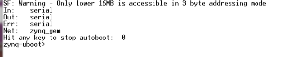
We should see something similar for U-boot output:

Screenshot from 2014-03-25 11:26:02

I will post some short videos and more pictures shortly from my zybo booting into u-boot.  The next step is to build the Linux kernel with the Xenomai patches, and compile our device tree.  I should have this up in the next couple of days.  There were numerous manual merges I had to make when applying the xenomai patches for some reason.  I may split it into two steps.

As always leave questions or comments here and I will do my best to get answer them!

Xilinx SDK and Create the First Stage Bootloader for Zybo

Hey All!!

We’ve got our design ready and built in Vivado.  The next step is to export this hardware design to the SDK and create a first stage boot loader that will will combine with the .bit file and uboot to create get the board to boot into the uboot shell.

Verify that you were able to create the bit file without problems, so generate it again and look at the output of Vivado.  Once that was been successfully generated let’s export the design to the SDK.

Screenshot from 2014-03-17 09:42:35

Right click your system.bd in your design sources and select ‘export hardware for SDK’, select a folder where we can export the design to and a workspace.  Make sure to check to box that asks if you would like to launch the SDK.  Also make sure to include the bit file checkbox, in my picture it’s not selected but it should be by default if you generate the bit stream before you export your hardware.

Screenshot from 2014-03-17 09:53:03

Make sure you have the block diagram open or there will be an error when the SDK launches.  When this error message occurs we see some prints in the console out : ‘”export_hardware” works only for active block diagrams’, so make sure your block diagram is active before we export it to the SDK.

Screenshot from 2014-03-19 09:25:07

Once the export is complete we should see the SDK open with an XML file that describes our system.

Screenshot from 2014-03-19 09:26:26

Next let’s create the first stage bootloader we will need to boot our board.  Select File -> New ->Application Project and enter a project name for our boot loader, I used zybo_fsbl.  The hardware platform should be filled in with the information that was exported from Vivado and make sure that under Board Support Package we have ‘Create New’ selected. Click Next and we should see some templates to choose from.  Select Zynq FSBL as the template project and hit ‘Finish’.

Screenshot from 2014-03-19 09:42:07

Once we clock finish the our first stage bootloader project and bsp should compile and be ready to go.  From here we could do some bare metal examples of a simple C program running on Zybo, I will probably come back to this later but for now let’s get U-boot compiled and ready to go.

Step 3 – building U-boot and creating a boot image is next and should be ready to post in a couple days.  Any questions please leave a comment or email me.  If you have questions about building Linux or booting the board feel free to ask them and I’ll answer them as soon as I can.  Those steps I’m hoping will be up next week.

Helpful Links:

http://www.zedboard.org/

http://www.zedboard.org/design/1521/11

Hardware design for Zybo

Let’s start by getting Vivado installed.  I used Xilinx Vivado to do my hardware design, it was easy to use and has all the programs we need built in.  My development environment was a Macbook pro running a VM for windows and one for Linux.  I could have done the whole thing in Linux, but at the time of me bringing Xenomai up I didn’t have ISE or Vivado installed in my Linux environment. I like CentOS for my Linux distro, it’s has a very nice and clean interface and I find it very stable.  It runs great in VM fusion, I will leave the Linux install to the reader but message me if you need help.

If you go to the Xilinx download page here you can choose the installer package you need, I choose the installer for both Linux and Windows.  The download is so big might as well grab both in case you need to change development environments later.  As mentioned this is a huge download so either do this at night or maybe grab a couple of cups of coffee while you wait.  Once you’ve got Vivado install it and select the defaults.  Zybo was recognized by both Linux and Windows with no problems.  Once Vivado is installed let’s go get the files we need from Digilent.  Dowload the ZYBO Board Definition File for configuring the Zynq Processing System core in Xilinx Platform Studio and Vivado IP Integrator and ZYBO Master XDC File for Vivado designs these two files will be needed in Vivado to create the initial hardware design.  Next let’s start up Vivado and create a new project.

Screenshot from 2014-03-13 11:09:54

Name your project, and select a place to put it, once that is done select RTL project and click next.

Screenshot from 2014-03-13 11:10:51

Click next for the next two dialogues, when asked to add a constraints file stop and let’s add the one that we downloaded from Digilent.

Screenshot from 2014-03-13 11:11:26

Screenshot from 2014-03-13 11:15:13

Screenshot from 2014-03-13 11:18:54

This should tell Vivado about the hardware we are going to use.  Next we need to tell Vivado what chip we are using, if we look back at the Digilent website for the Zybo we can make a note of the following information:

The ZYBO offers the following on-board ports and peripherals:

  • ZYNQ XC7Z2010-1CLG400C
  • 512MB x32 DDR3 w/ 1050Mbps bandwidth
  • Dual-role (Source/Sink) HDMI port
  • 16-bits per pixel VGA output port
  • Trimode (1Gbit/100Mbit/10Mbit) Ethernet PHY
  • MicroSD slot (supports Linux file system)
  • OTG USB 2.0 PHY (supports host and device)

The top line is what we want and will help us identify the chip.  From the drop down menus select Zynq-7000 for Family, Zynq-7000 for sub family, clg400 for package, -1 for speed grade and C for temp grade.  You will have two choices left xc7z010clg-400-1 and xc7z020clg400-1, choose the fist one since your Zynq chip is the Xilinx Zynq-7000 (Z-7010) as mentioned on the Digilent website.  You also want to grab the hardware guide for Zybo, it will help in future posts if you are following along.

Screenshot from 2014-03-13 11:20:33

We are ready to confirm and create the project

Screenshot from 2014-03-13 11:23:34

So we should now have Vivado open with a new project like the picture below.

Screenshot from 2014-03-13 11:44:44

Now we are ready to create the block diagram and add some IP.

In the left side of the screen click on create block design.  I named my block design system but I don’t think the name really matters.

Screenshot from 2014-03-13 11:47:29

Now that we have a new block design, we can go ahead and add some IP to it.  Click Add IP on the green highlight that appeared in the diagram window. Scroll down and select Zynq7 Processing System.

Screenshot from 2014-03-13 11:48:47

Press Enter and you should now see a Zynq processor on your block design.

Screenshot from 2014-03-13 11:49:14

So far so good, let’s double-click the Zynq block and customize our IP to the Zybo.

Screenshot from 2014-03-13 11:49:43

Now let’s import the XPS settings that we downloaded from the Digilent site that will describe our hardware, click the import XPS settings button

Screenshot from 2014-03-13 11:50:06

Select the .xml file that we downloaded from Digilent, click OK.  Now click OK in the import XPS settings window.

Screenshot from 2014-03-13 11:50:21

So we now see some check marks beside some peripherals.  Let’s take a second and look at the clock configuration.  Click the clock configuration in the left side of the window, you should see something like the picture below.

Screenshot from 2014-03-13 11:51:16

Make a note of the input frequency.  This is DIFFERENT from both Zedboard and MicroZed and can cause some really frustrating problems when trying to add correct features to the device tree when we boot Linux.  I’ll explain what I ran into when we go over how to get Xenomai/Linux to boot. Click Ok and the customization screen should close and our processor should now have some inputs and outputs.

Screenshot from 2014-03-13 11:51:59

Connect the FCLK_CLK0 to the M_AXI_GP0_ACLK, once we scroll over the input a pencil appears and then connect each input similar to Labview if anyone has used that before.

Screenshot from 2014-03-13 11:54:10

This pretty much just feeds a clock to the FPGA and is the most basic FPGA design we can do.  I’m not a FPGA expert and plan to use the Zybo to further my learning when it comes to FPGA design.  I believe this pretty much brings the FPGA up and nothing else, so nothing on the FPGA is being used.  Let’s validate our design, before we start to create the HDL wrappers and bit file. Run the Block Automation as suggested by the green highlight.

Screenshot from 2014-03-13 11:58:23

Click the sources tab on the block design and right-click the system.bd file and select Create HDL Wrapper.

Screenshot from 2014-03-13 12:04:55

Once that is complete we should see some Verilog or VHDL files.  Now we can go ahead and generate the bitstream file, this should be on the left side of the screen near the bottom.

Screenshot from 2014-03-13 12:09:49

Once we are done, we can open the implemented design.

Screenshot from 2014-03-13 12:12:37

We are pretty much done!  The next step is to export our design to the Xilinx SDK to create the first stage bootloader.  This will be the subject of my next post.  Remember to save your project since we’ll need it in my next post.

If anyone runs into problems let me know I may have a step or two out-of-order, but I was able to create the bit file again following these steps.  Questions and comments are always welcome.

Helpful links:

http://www.wiki.xilinx.com/

http://forums.xilinx.com/t5/Xcell-Daily-Blog/Bringing-up-the-Avnet-MicroZed-with-Vivado/ba-p/362901

-Greg

Getting Started with Zybo

Over the next couple of weeks I will post steps on how to get your Zybo ready to run Xenomai.  Here are the steps that are needed to get your Zybo ready to run Xenomai (or regular Linux).

  • Create a design in Vivado for Zybo
  • Create the First Stage Bootloader
  • Build u-boot
  • Create the boot image
  • Checkout and patch Xilinx Linux with Xenomai  (this stage got tricky)
  • Compile the Linux Kernel with Xenomai support
  • Compile the Xenomai user space support
  • Create a rootfs
  • Prepare the SDCard
  • Run the Xeno latency test

I probably forgot a step so that list might change.  It sounds like a lot but it’s pretty straight forward once you uncover some of the tricks.  I found that the hardware guide for Zybo is your friend when trying to figure out why things for the Zedboard won’t work right out of the box.  I will start the first post in a few minutes and hopefully have it up in a couple hours and I’m aiming to have all the steps done very soon.

Thanks to all who read this, leave comments or questions


-Greg


Xenomai on Zybo

Hi All,

This is my first blog and blog post for that matter.  This blog will be dedicated to embedded system and maybe some other fun software things.  For now I’m putting the finishing touches on my first real post which will be an introduction on how to get a Zybo Zynq board from Digilent up and running from scratch with first Linux and then with Xenomai Linux.  I should have part one ready in two weeks.

-Greg