Let’s start by getting Vivado installed. I used Xilinx Vivado to do my hardware design, it was easy to use and has all the programs we need built in. My development environment was a Macbook pro running a VM for windows and one for Linux. I could have done the whole thing in Linux, but at the time of me bringing Xenomai up I didn’t have ISE or Vivado installed in my Linux environment. I like CentOS for my Linux distro, it’s has a very nice and clean interface and I find it very stable. It runs great in VM fusion, I will leave the Linux install to the reader but message me if you need help.
If you go to the Xilinx download page here you can choose the installer package you need, I choose the installer for both Linux and Windows. The download is so big might as well grab both in case you need to change development environments later. As mentioned this is a huge download so either do this at night or maybe grab a couple of cups of coffee while you wait. Once you’ve got Vivado install it and select the defaults. Zybo was recognized by both Linux and Windows with no problems. Once Vivado is installed let’s go get the files we need from Digilent. Dowload the ZYBO Board Definition File for configuring the Zynq Processing System core in Xilinx Platform Studio and Vivado IP Integrator and ZYBO Master XDC File for Vivado designs these two files will be needed in Vivado to create the initial hardware design. Next let’s start up Vivado and create a new project.

Name your project, and select a place to put it, once that is done select RTL project and click next.

Click next for the next two dialogues, when asked to add a constraints file stop and let’s add the one that we downloaded from Digilent.
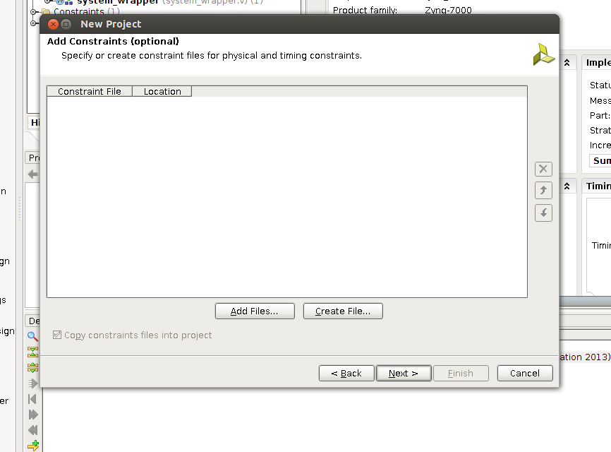

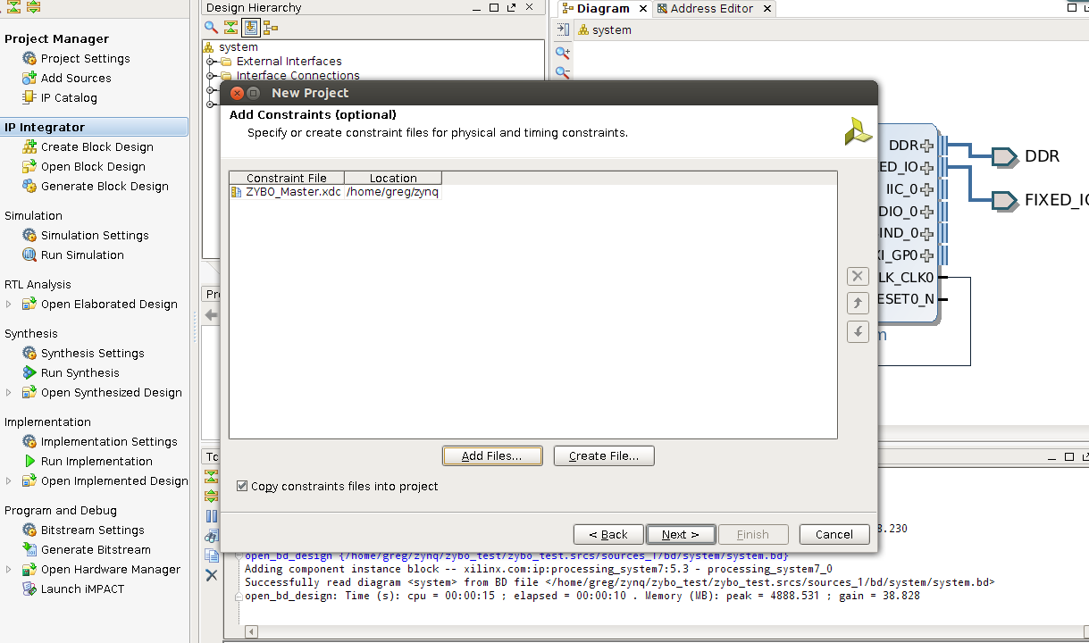
This should tell Vivado about the hardware we are going to use. Next we need to tell Vivado what chip we are using, if we look back at the Digilent website for the Zybo we can make a note of the following information:
The ZYBO offers the following on-board ports and peripherals:
- ZYNQ XC7Z2010-1CLG400C
- 512MB x32 DDR3 w/ 1050Mbps bandwidth
- Dual-role (Source/Sink) HDMI port
- 16-bits per pixel VGA output port
- Trimode (1Gbit/100Mbit/10Mbit) Ethernet PHY
- MicroSD slot (supports Linux file system)
- OTG USB 2.0 PHY (supports host and device)
The top line is what we want and will help us identify the chip. From the drop down menus select Zynq-7000 for Family, Zynq-7000 for sub family, clg400 for package, -1 for speed grade and C for temp grade. You will have two choices left xc7z010clg-400-1 and xc7z020clg400-1, choose the fist one since your Zynq chip is the Xilinx Zynq-7000 (Z-7010) as mentioned on the Digilent website. You also want to grab the hardware guide for Zybo, it will help in future posts if you are following along.

We are ready to confirm and create the project

So we should now have Vivado open with a new project like the picture below.

Now we are ready to create the block diagram and add some IP.
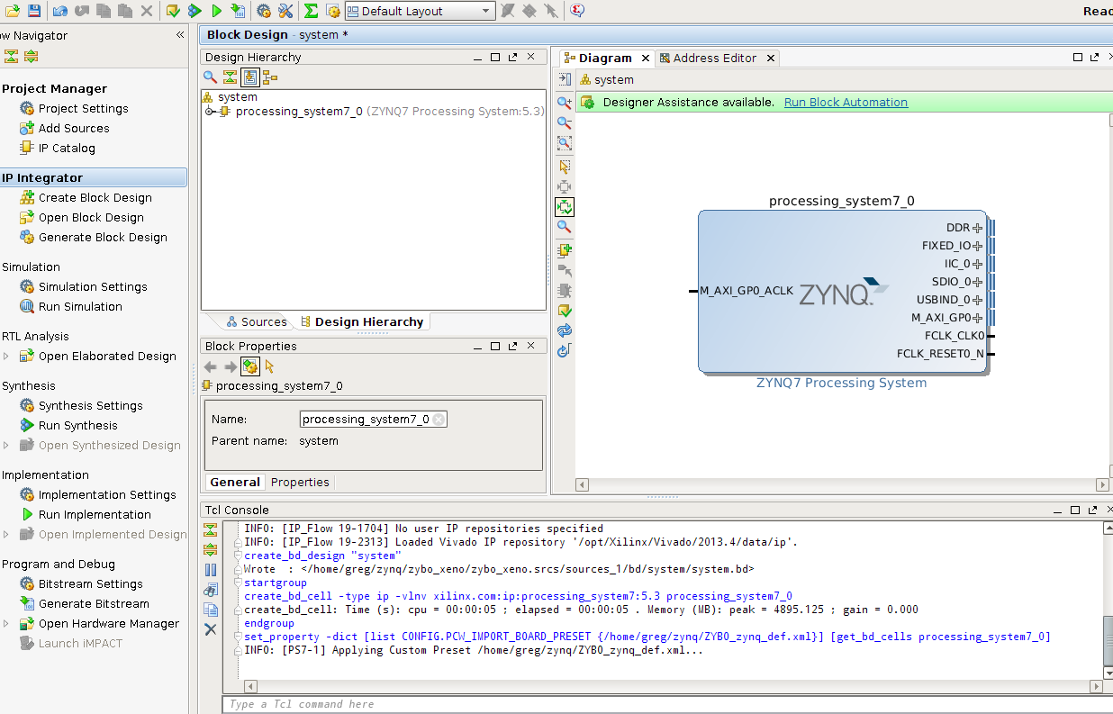
In the left side of the screen click on create block design. I named my block design system but I don’t think the name really matters.

Now that we have a new block design, we can go ahead and add some IP to it. Click Add IP on the green highlight that appeared in the diagram window. Scroll down and select Zynq7 Processing System.

Press Enter and you should now see a Zynq processor on your block design.

So far so good, let’s double-click the Zynq block and customize our IP to the Zybo.

Now let’s import the XPS settings that we downloaded from the Digilent site that will describe our hardware, click the import XPS settings button

Select the .xml file that we downloaded from Digilent, click OK. Now click OK in the import XPS settings window.

So we now see some check marks beside some peripherals. Let’s take a second and look at the clock configuration. Click the clock configuration in the left side of the window, you should see something like the picture below.

Make a note of the input frequency. This is DIFFERENT from both Zedboard and MicroZed and can cause some really frustrating problems when trying to add correct features to the device tree when we boot Linux. I’ll explain what I ran into when we go over how to get Xenomai/Linux to boot. Click Ok and the customization screen should close and our processor should now have some inputs and outputs.
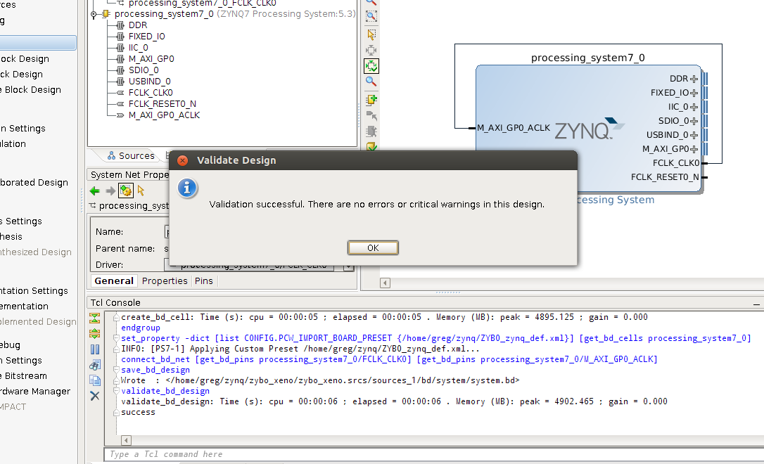
Connect the FCLK_CLK0 to the M_AXI_GP0_ACLK, once we scroll over the input a pencil appears and then connect each input similar to Labview if anyone has used that before.

This pretty much just feeds a clock to the FPGA and is the most basic FPGA design we can do. I’m not a FPGA expert and plan to use the Zybo to further my learning when it comes to FPGA design. I believe this pretty much brings the FPGA up and nothing else, so nothing on the FPGA is being used. Let’s validate our design, before we start to create the HDL wrappers and bit file. Run the Block Automation as suggested by the green highlight.
Click the sources tab on the block design and right-click the system.bd file and select Create HDL Wrapper.

Once that is complete we should see some Verilog or VHDL files. Now we can go ahead and generate the bitstream file, this should be on the left side of the screen near the bottom.

Once we are done, we can open the implemented design.

We are pretty much done! The next step is to export our design to the Xilinx SDK to create the first stage bootloader. This will be the subject of my next post. Remember to save your project since we’ll need it in my next post.
If anyone runs into problems let me know I may have a step or two out-of-order, but I was able to create the bit file again following these steps. Questions and comments are always welcome.
Helpful links:
http://forums.xilinx.com/t5/Xcell-Daily-Blog/Bringing-up-the-Avnet-MicroZed-with-Vivado/ba-p/362901
-Greg

Hello Grec,
Vivado is sufficient to programm the process of the Zynq (dual core ARM) ? Or there is other environment to install ?
Hi Greg,
the operation sequence is well described and works fine.
Thanks a lot,
PaoloC
Can you provide a Verilog example within Vivado how to switch leds, or present the state of the switches to ARM via FPGA fabric ?
Is Xenomai is best choice ? What are the other RTOS options and why did you opt for this one ?
I am lookin forward to your next post, as I am interested in setting up Debian.
Dear Greg,
I am not sure if you had a look, or did any progress with Zybo board, but I made a custom image and I am stucked with baudrate fliping to probably 9600.
The problem is that u-boot starts with baudrate 115200, and bootargs are set to console=ttyPS0,115200 but even though after kernel is uncompressed baudrate changes to something else and I get gibberish on the screen.
Please let me know about your progress, or maybe I can share how I solved issues on the way to reach this point.
Regards
Hi Mateusz,
The issue you are seeing is sort of a baudrate problem. I ran into the same thing. The PLL clock on the Zybo is 50 MHZ, on Zebboard and microZed it’s 33.3Mhz. If you are configuring Linux using the zedboard device tree change the clock that is used for the UARTs from 33.3Mhz to 50Mhz. This was the most frustrating part of bringing the board up with Linux. If you can’t find the line in the devicetree file in the Linux Kernel source i can post it.
-Greg
Hi Greg,
when will you post step 2 ?
Thanks a lot.
Saber
Step 2 should be posted late this afternoon hopefully.
Will it include custom hardware design ? I didn’t use device tree from zedboard, I generated one in SDK (device tree bsp) based on the project exported from Vivado.
In your device tree what speed do you have for your ps_clk? What Linux tree are you using to compile from, are you compiling from a branch or tag?
Which version of Vivado are you using? I tried with 2014.2 but generating the bitstream fails. It actually fails during the synthesis “Synthesis failed” but does not produce any errors. The Log does not reveal anything either. Any ideas?
It was 2013.4, I’ll try with 2015.1
Do you recommend to work with the ZYBO in Linux or Windows? Or what are the advantages or disadvantages of working with either? Thank you very much.
I would work work with Linux if you are going to be trying to build a linux distro
Hi Greg
I followed your steps
But when I run block design i don’t get Validation sucessful message. Instead I get below message
connect_bd_net [get_bd_pins processing_system7_0/FCLK_CLK0] [get_bd_pins processing_system7_0/M_AXI_GP0_ACLK]
[Boardtcl 53-1] No current board_part set.
Still I continued with the steps.
In the next tutorial you ask to Right click your system.bd in your design sources and select ‘export hardware for SDK’
I am not able to find export hardware for SDK.
Please help.
Thanks & Regards,
Ajith
I’ll look into it, what version of vivado are you using?
HI
I done some example in vivado and how to add zynq processsor to it and my problem is to program on flash. is it possible or not?
I’m not sure I follow your problem, in vivado you should be able to flash the PL, I’ve never tried flashing the linux image straight to RAM